Sensors and OOP
Project Overview
This project combines two different sensor implementations using object-oriented programming principles. First, I created and programmed a capacitive sensor that responds to applied force, providing visual feedback through LED lights and audio feedback through a buzzer. As force is applied, the LED changes color, and if too much force is detected, the system beeps and shows a red warning light. Second, I implemented an MPU6050 gyroscope sensor that monitors rotational motion and orientation, providing real-time data for motion analysis. This implementation will be crucial for the final smart headgear project, where precise motion tracking is essential for impact detection and analysis.
Capacitive Sensor Project
Capacitive Sensor Demonstration
Sensor Design
Created a capacitive sensor that measures applied force and converts it into electrical signals.
Visual Feedback
Implemented LED color changes based on force levels:
- Normal force: Green light
- Increased force: Yellow light
- Excessive force: Red light with buzzer
Programming
Developed the code to:
- Read sensor values
- Process force measurements
- Control LED colors
- Trigger buzzer for warnings
MPU6050 Gyroscope Project
Sensor Implementation
Implemented the MPU6050 gyroscope sensor using object-oriented programming principles to create a reusable and maintainable codebase.
Motion Tracking
The system monitors:
- Rotational movement on all axes
- Acceleration data in three dimensions
- Temperature readings for calibration
Data Processing
Developed real-time data processing capabilities:
- Motion threshold detection
- Impact force calculation
- Orientation tracking
Results
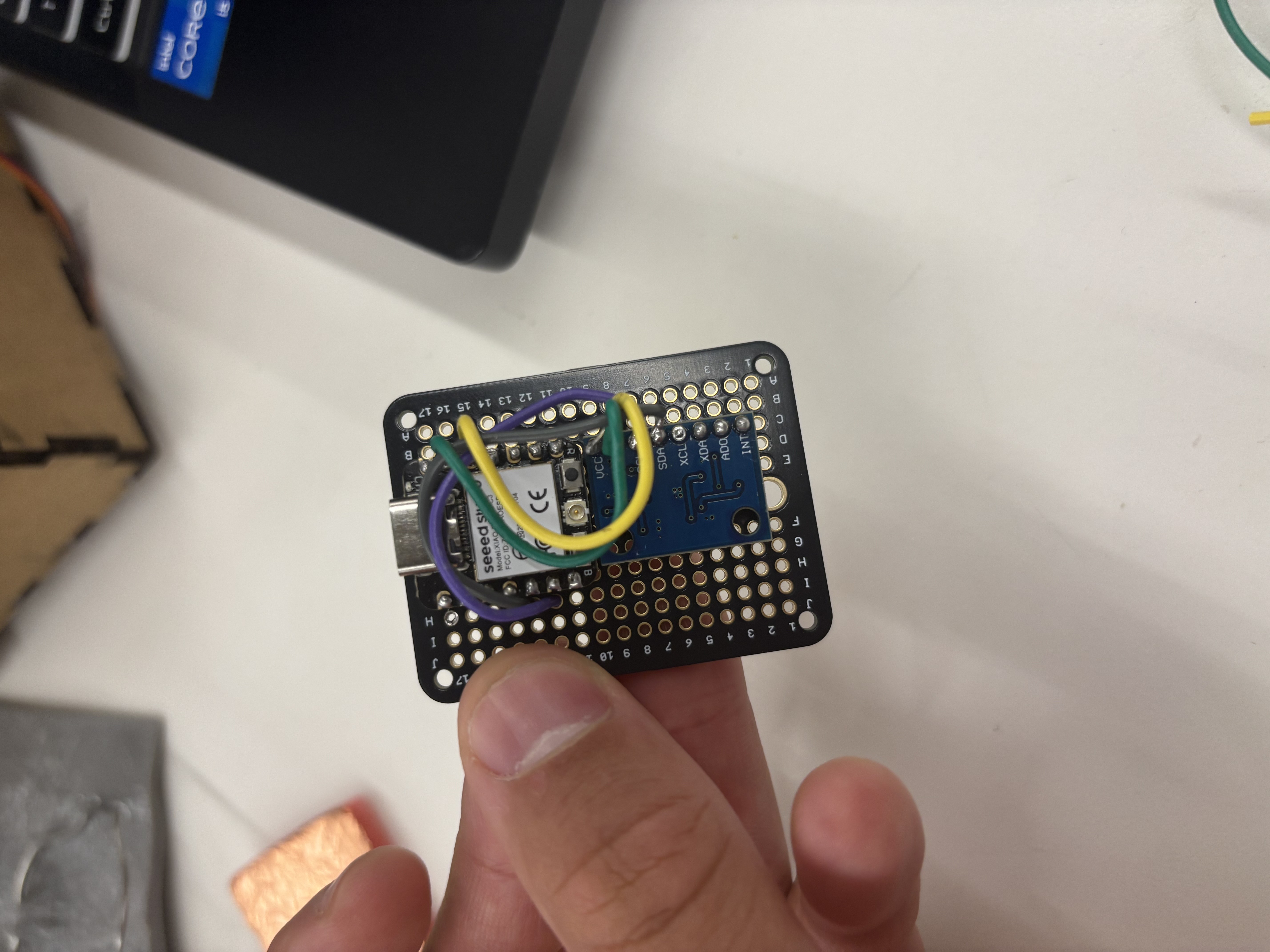
MPU6050 Gyroscope sensor implementation
Arduino Code
#include <Wire.h>
#include <Adafruit_MPU6050.h>
#include <Adafruit_Sensor.h>

class MotionSensor {
private:
    Adafruit_MPU6050 mpu;
    const int ledPin = 13;
    float threshold = 2.0; // Motion threshold in m/s^2

public:
    MotionSensor() {
        pinMode(ledPin, OUTPUT);
    }

    bool begin() {
        if (!mpu.begin()) {
            return false;
        }
        mpu.setAccelerometerRange(MPU6050_RANGE_8_G);
        mpu.setGyroRange(MPU6050_RANGE_500_DEG);
        mpu.setFilterBandwidth(MPU6050_BAND_21_HZ);
        return true;
    }

    void update() {
        sensors_event_t a, g, temp;
        mpu.getEvent(&a, &g, &temp);

        // Calculate total acceleration
        float totalAccel = sqrt(a.acceleration.x * a.acceleration.x +
                              a.acceleration.y * a.acceleration.y +
                              a.acceleration.z * a.acceleration.z);

        // Update LED based on motion
        digitalWrite(ledPin, totalAccel > threshold);

        // Print data for calibration
        Serial.print("Acceleration X: ");
        Serial.print(a.acceleration.x);
        Serial.print(", Y: ");
        Serial.print(a.acceleration.y);
        Serial.print(", Z: ");
        Serial.print(a.acceleration.z);
        Serial.print(" m/s^2");
        Serial.println();
    }
};

MotionSensor sensor;

void setup() {
    Serial.begin(115200);
    while (!Serial) delay(10);

    if (!sensor.begin()) {
        Serial.println("Failed to find MPU6050 chip");
        while (1) {
            delay(10);
        }
    }
    Serial.println("MPU6050 Found!");
}

void loop() {
    sensor.update();
    delay(100); // Small delay for readability
}
Circuit Schematic

MPU6050 connection schematic with Arduino
Wiring Instructions
- VCC → 5V
- GND → GND
- SCL → A5
- SDA → A4
- LED → Pin 13
Sensor Calibration & Data Visualization
Real-time Data Processing
The MPU6050 sensor data is processed and sent to Firebase in real-time, where it's visualized through a custom web interface. The system includes:
- Live impact force monitoring
- Real-time gyroscope readings
- Impact distribution analysis
- Session statistics and metrics
Live Data Dashboard
Smart Strike Monitoring System
The data from the MPU6050 sensor is processed and displayed in real-time on our custom dashboard. The system provides:
- Impact force measurements in G-force
- Gyroscope orientation data
- Impact rate and distribution analysis
- Session statistics and safety controls
Live Dashboard Preview
Live monitoring dashboard for impact analysis